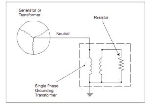
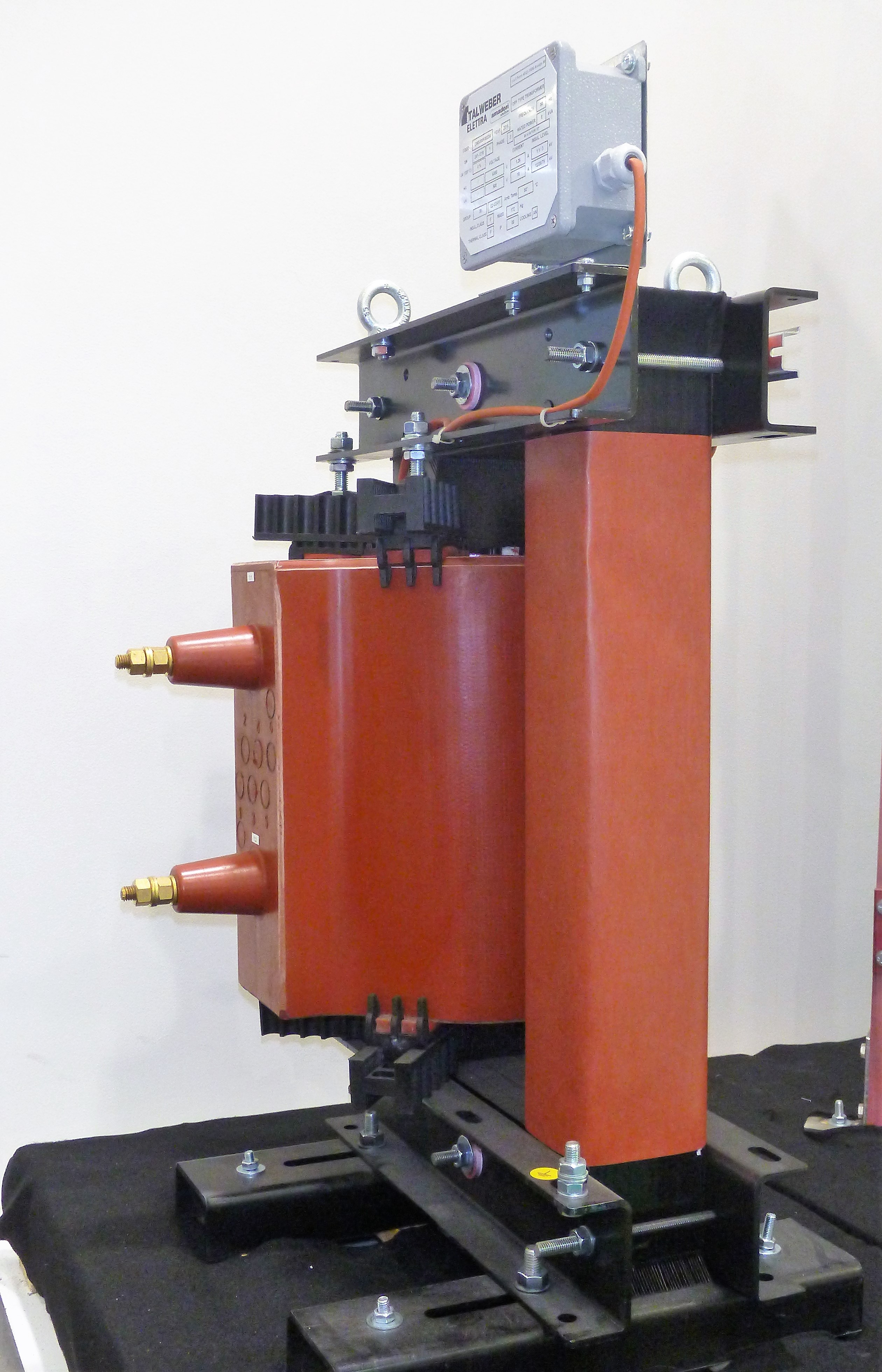
The earthing transformer is typically connected between the star center of a three-phase generator and the earth.
As illustrated in the drawing below, is the primary that, connected in series to the generator and ground, set up an impedance that may be more or less high depending on the type of the load that will be connected to the secondary circuit.
In this way, it is possible to limit the primary fault current by using a resistance with low ohmic value. It will then have the benefit of attenuating the fault current and reduce the values of transient overvoltages. A product with these characteristics is much cheaper and more manageable than the MT one in terms of power.
Depending on the destination of the transformer it is possible to connect to the secondary a resistance or a reactance, according to the type of load the behavior of the transformer will also vary during the failure.
The benefit therefore lies in being able to limit the fault currents giving the necessary time for the protections to intervene. Voltage transients are also attenuated by a system that can withstand a high number of faults without losing efficiency.
Characteristics data:
Type= Cast Resin Earthing Transformers
Pn=8 kVA continuous / 80 kVA for 10 sec. fault
Primary Voltage = 6350 V
Secondary Voltage = 500 V
Frequency = 50 Hz
Insulation level = 12/28/75 kV
Thermal/Insulation class = F/F
Cooling = Air Natural
Ambient Temperature = 50 °C


